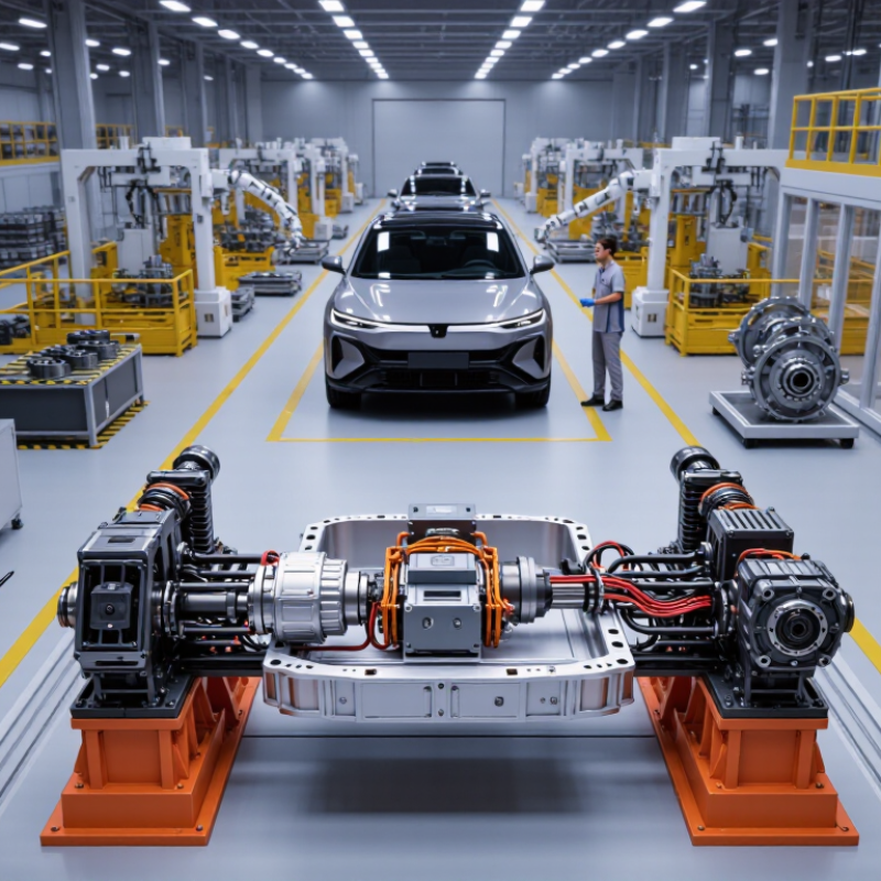
| E-Axle Architecture | Integrated systems commonly combine an electric motor, inverter, single-speed reducer, differential, housing, lubrication system, and control interfaces. | Confirm whether the motor, inverter, reducer, and differential are developed and validated as one matched system rather than assembled from unrelated components. | A higher level of integration can reduce packaging volume, wiring, assembly steps, and system losses. | Review system architecture drawings and interface specifications. |
| Drive Configuration | Front-wheel-drive, rear-wheel-drive, and dual-motor all-wheel-drive layouts are widely used in battery electric vehicles. | Check axle orientation, differential arrangement, half-shaft geometry, mounting points, ground clearance, and compatibility with the vehicle platform. | Incorrect geometry may cause installation delays, vibration, or interference with the chassis and suspension. | Request a 3D installation model and vehicle interface drawing. |
| High-Voltage Platform | Passenger EV systems commonly use approximately 200–450 V, while higher-voltage platforms may operate around 600–900 V. | Verify nominal voltage, maximum operating voltage, insulation coordination, connector ratings, creepage and clearance, and compatibility with the battery and charging system. | Voltage compatibility affects charging performance, current demand, cable size, inverter design, and safety compliance. | Compare the complete high-voltage electrical specification. |
| Continuous and Peak Power | Light-duty EV e-axles may range from approximately 50–150 kW, while passenger-car systems can commonly reach about 100–250 kW per axle. | Request power curves against motor speed, battery voltage, coolant temperature, and defined test duration. | Peak power supports acceleration; continuous power determines sustained hill climbing, towing, and high-speed operation. | Evaluate both peak and continuous ratings, not peak power alone. |
| Output Torque | Typical passenger-vehicle e-axle peak output torque may be approximately 1,000–4,000 N·m at the axle output, depending on vehicle mass and reduction ratio. | Confirm peak torque duration, continuous torque, speed range, torque ripple, and whether the figure is motor-shaft torque or wheel-side output torque. | Torque affects launch performance, gradeability, towing capability, and low-speed control. | Use the vehicle load, tire radius, and target grade to calculate required wheel torque. |
| Motor Technology | Permanent-magnet synchronous motors are widely used; induction and electrically excited motors are also applied in selected vehicle designs. | Check motor type, magnet retention, demagnetization protection, rotor balance, winding process, and operating temperature limits. | Motor selection influences efficiency, cost, thermal behavior, rare-earth material exposure, and controllability. | Review motor design calculations and end-of-line test coverage. |
| Operating Efficiency | Well-designed motor-inverter-reducer systems can achieve peak system efficiency above 90%; actual efficiency varies with speed, torque, temperature, and voltage. | Require efficiency maps for the motor, inverter, reducer, and complete e-axle under representative drive cycles. | Higher efficiency improves driving range and reduces heat generation and cooling demand. | Compare full operating maps rather than a single maximum-efficiency value. |
| Reduction Ratio | Single-speed EV reducers commonly use fixed ratios broadly within approximately 7:1–12:1, depending on motor speed and vehicle requirements. | Verify ratio accuracy, gear design, tooth contact, bearing loads, lubrication method, and allowable input speed. | The ratio balances launch torque, top speed, motor operating efficiency, noise, and package size. | Match the ratio to tire diameter, vehicle mass, motor speed, and target maximum speed. |
| Thermal Management | Liquid cooling is common for the motor and inverter; some designs use shared or separate coolant circuits for improved temperature control. | Check coolant type, flow rate, pressure drop, inlet temperature, thermal interface design, and derating strategy. | Thermal performance controls sustained output, component life, efficiency, and driving consistency. | Request thermal test reports at low, normal, and high ambient temperatures. |
| Ingress Protection | Vehicle-mounted high-voltage drive units are often designed to meet high dust and water protection levels, commonly including IP6K7 or IP6K9K where specified by the vehicle program. | Verify the exact protection rating, test method, pressure-wash conditions, connector sealing, vent design, and post-test insulation resistance. | Protection against dust, water immersion, and high-pressure cleaning is essential for vehicle durability and electrical safety. | Require independent or witnessed environmental test evidence. |
| NVH Performance | Important noise sources include electromagnetic whine, gear mesh noise, bearing noise, structural vibration, and inverter switching noise. | Ask for sound-pressure data, order-tracking results, gear microgeometry controls, balancing limits, and test conditions. | EV powertrains have less engine masking noise, making gear and electromagnetic noise more noticeable. | Assess NVH using the intended vehicle mounting system and representative operating points. |
| Functional Safety | Automotive drive systems are commonly developed with ISO 26262 processes; the required Automotive Safety Integrity Level depends on the vehicle safety concept. | Verify hazard analysis, safety goals, diagnostic coverage, fault reaction, torque monitoring, safe-state behavior, and safety documentation. | Functional-safety engineering reduces risks related to unintended torque, loss of propulsion, and high-voltage faults. | Evaluate process capability and project-specific safety deliverables. |
| Cybersecurity and Software | Modern vehicle electronic systems increasingly use cybersecurity engineering aligned with ISO/SAE 21434 and software update controls aligned with vehicle-program requirements. | Check CAN or automotive Ethernet interfaces, diagnostic services, secure boot, access control, software version management, and vulnerability response procedures. | Secure software prevents unauthorized commands and supports long-term vehicle maintenance. | Review the supplier’s software-development and cybersecurity lifecycle. |
| Validation and Reliability | Validation normally includes performance, endurance, thermal cycling, vibration, shock, corrosion, water exposure, insulation, overspeed, and abuse testing. | Request a design-validation plan, production-validation plan, failure-mode analysis, accelerated-life assumptions, and corrective-action records. | A complete validation program demonstrates durability beyond prototype-level performance. | Give priority to suppliers with repeatable, traceable test evidence. |
| Manufacturing Quality System | Automotive production suppliers are generally expected to operate an IATF 16949-based quality management system, supported by process controls and documented traceability. | Verify certification scope, process audits, control plans, statistical process control, measurement-system analysis, and nonconformance handling. | Quality-system maturity affects consistency, field reliability, launch risk, and warranty exposure. | Conduct a technical and manufacturing-site audit before nomination. |
| Production Capacity | Capacity varies by automation level, shift pattern, line configuration, product complexity, and customer forecast; no universal capacity figure applies. | Confirm monthly installed capacity, current utilization, bottleneck processes, expansion plan, equipment redundancy, and supplier capacity reservation. | Insufficient capacity can cause delivery delays and reduce the ability to support vehicle-production ramp-up. | Compare demonstrated output with the project’s launch and peak-volume requirements. |
| Supply-Chain Control | Critical inputs may include electrical steel, copper winding materials, permanent magnets, power semiconductors, bearings, gears, seals, sensors, and control electronics. | Assess second-source coverage, component lead times, material traceability, semiconductor allocation, change-control procedures, and business-continuity planning. | Supply-chain resilience reduces production interruptions and uncontrolled component substitutions. | Require a risk-ranked bill of materials and approved-source list. |
| Customization Capability | Common customization areas include mounting interfaces, axle width, gear ratio, motor winding, cooling connections, software calibration, connectors, and vehicle communication protocols. | Verify engineering resources, design-change lead time, prototype capability, calibration tools, intellectual-property ownership, and validation responsibility. | Customization determines how effectively the e-axle can be integrated into a specific vehicle platform. | Score the supplier on engineering depth, not only on catalog specifications. |
| Commercial and Lifecycle Support | A complete sourcing evaluation should cover prototype cost, tooling, unit price, logistics, warranty policy, spare parts, service response, and end-of-life support. | Request a transparent cost breakdown, warranty assumptions, field-failure process, spare-parts availability, technical-support coverage, and total-cost-of-ownership estimate. | The lowest purchase price may not provide the lowest lifecycle cost if reliability, service, or integration risks are high. | Use a weighted scorecard combining technical, quality, delivery, and lifecycle cost factors. |